Pinouts (Wiring Schemes)


“Pinout” is a term describing how an electrical cable is wired. Some cables do not have pinouts because they only contain a single internal wire, like coax cables. But if a cable has multiple pins on the end of the cable, it will have a pinout.
Each type of multi-pin cable has a standard pinout or two, but these layouts are not set in stone. Some machines will require non-standard pinouts; this will require users to use a custom cable.
Pinouts also come into play when using a cable with two different ends. For example, going from DB9 (9 pins) to DB25 (25 pins) will mean the DB25 side has 16 unused, “dead” pins.
If you need to know what pinout a cable needs, ideally there will be a spec sheet handy showing it. The next best option is contacting the manufacturer of the equipment the cable will be used with to see if they have a spec sheet available. If you have a cable tester available, that can be used to see how the pins line up. As a last resort, a cable can also be cut open to verify the pinout.
In the guide below, we will be highlighting the standard pinout configuration for common types of multi-pin cables.
Ethernet Pinouts
Ethernet uses two main pinouts, straight and crossover. Straight cables are used to connect computers to other devices, like modems and routers. Crossover cables are used to connect two computers directly. The wires inside ethernet cables are color-coded to industry standards, making it easy to follow the standard pinout options.
Straight pinouts are divided into two different options, T-568A and T-568B. The “B” option is the standard today, although finding the “A” cables still in use in older buildings is not uncommon. The two options are incompatible so make sure to verify what any existing cables use before adding on new ones.
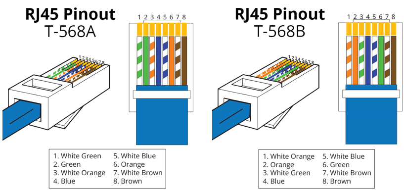
A crossover cable uses two different RJ45 color codes (pinouts) on either end of the cable. Typically, this is done by using T-568A on one side and T-568B on the other. This allows two computers to talk to each other directly via ethernet. If you try to use a straight pinout cable the same way both computers will be trying to “talk” and “listen” to each other at the same time, so nothing will happen.

Telephone Pinouts
Telephone pinouts are similar to ethernet, with RJ11 and RJ12 phone connectors looking like downsized versions of the RJ45 connectors used for ethernet. RJ11 and RJ12 are the same size; the difference is that RJ11 can only use four wires while RJ12 can use six. Cables today are typically made as RJ12 but plenty of older cables made with RJ11 are still in place in older buildings.
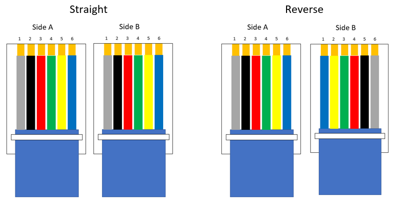
Phone pinouts come in two varieties, straight and reverse. Straight cables are used to send data, like a fax machine, while reverse cables are used for voice, like a telephone. On a straight cable, the wires will connect to the same metal pins on either side of the cable. Pin 1 to pin 1, pin 2 to pin 2, etc. On a reverse cable, the opposite is true. For RJ12, a reverse cable would go pin 1 to pin 6, pin 2 to pin 5, etc.
Serial (DB) Pinouts
Serial cables, also called DB or D-Sub (D-Subminiature), are a dying breed. For the most part, they have been replaced by USB, but older machinery still uses them. There are a few main types of serial cables: DB9, DB15, and DB25.
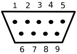
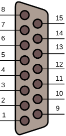
DB9 is the old standard for monitors and was later replaced by VGA. The nine pins are in two rows with five on top and four on the bottom. The pins are counted from left to right, starting with the top row. For a straight-through cable, pin 1 connects to pin 1, then 2 to 2, 3 to 3, etc. Here is a DB9 connector pinout to explain more fully.
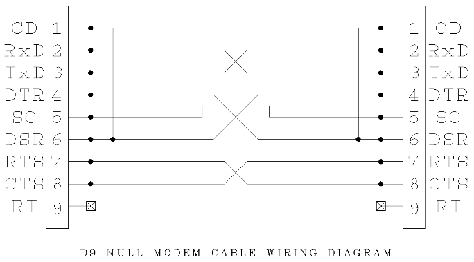
There is also a version of DB9 called null modem, which is an older version of crossover ethernet. Null modem cables allow computers and other machines to speak to each other directly.
DB15 is divided into two rows with eight pins on top and seven on the bottom, as opposed to the three rows seen on VGA cables. These connections used to be used on sound cards as well as old Mac monitors.
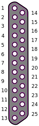
DB25, also called a parallel port, was standard on older printers before being replaced by USB B as the new industry standard.
VGA Pinouts
VGA cables are the previous standard for monitors and were the last dedicated analog connection. Newer equipment uses digital connections like HDMI, DisplayPort, and DVI instead. Plenty of monitors and other equipment built with VGA are still around, it is just not put onto new machines anymore.
A VGA pinout contains 15 pins, broken into three rows of 5. There are some VGA ports where Pin 14 is not used. Likewise, there are some VGA cables where the 14th pin is a “dead pin”; a pin not actually connected to anything or left out entirely. If your equipment needs the full 15-pin set-up or you want to keep your bases covered, make sure to purchase a True 15-Pin cable.

DVI Pinouts
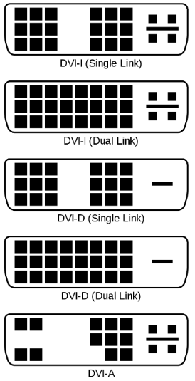
There are three main versions of DVI cables: DVI-A (Analog), DVI-D (Digital), and DVI-I (Integrated; Analog + Digital). DVI-D and DVI-I also come in single-link and dual-link variants. The pin layout on each type is a bit different, which is the easiest way to tell different DVI cables apart.
DVI-A is analog only, making it compatible with older devices that only have VGA.
DVI-D is digital only. The single-link version can support resolutions up to 1920 x 1080 while the dual-link version can handle up to 2048 x 1536 resolution.
DVI-I combines the other two to support both analog and digital. It also comes in single-link and dual-link, both of which support 1600 x 1200 (single-link) and 2048 x 1536 (dual-link) resolutions.
3.5mm Pinouts
3.5mm, also called headphone or ⅛”, is a common audio cable. This is the go-to audio connection found on computers, cell phones, televisions, and more. 3.5mm is built the same way as 2.5mm (which is smaller) and ¼” (which is bigger). Pinouts for 3.5mm can be applied to those two as well.
There are a few different versions of 3.5mm: TS, TRS, and TRRS. TS cables will have one ring, dividing the metal sections into two conductors and are most often used for mono connections like microphones. TRS has two rings to give it three conductors, allowing them to be used for stereo connections such as speakers. TRRS has three rings for four conductors to support stereo audio and a mono microphone at the same time.
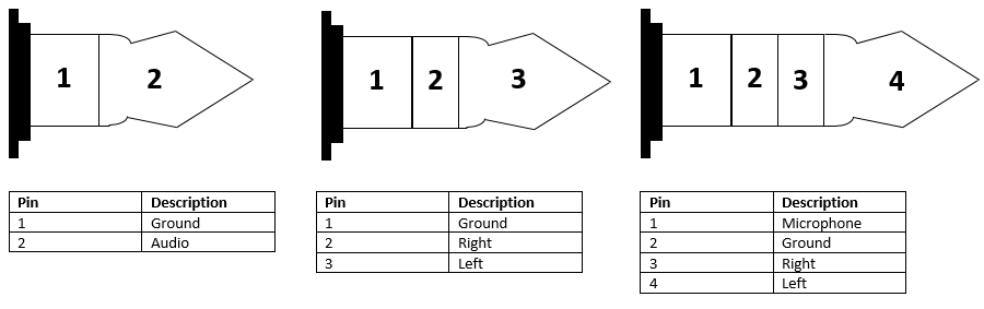
Mono (left), Stereo (middle), and Headset (right; microphone+stereo) are all industry standards
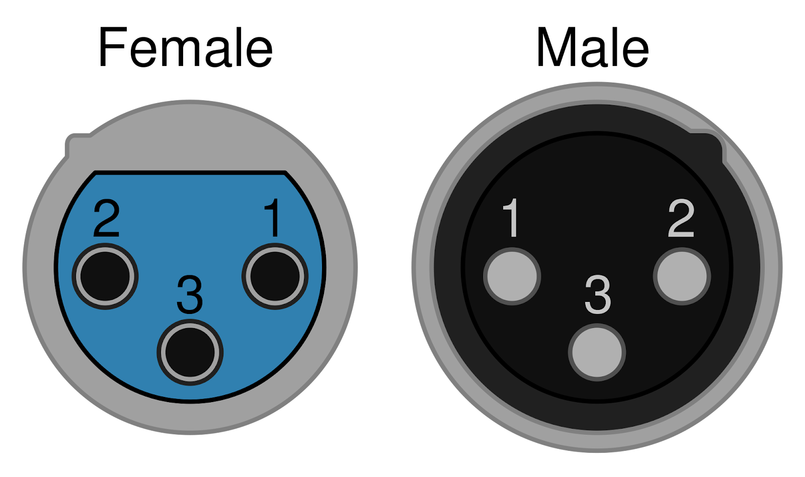
XLR Pinouts
XLR is a type of professional audio cable with a few different variants, the most common being 3-pin XLR. The pins in this are used for left audio, right audio, and a ground. If additional connections need to be made, using other versions of XLR with more pins can compensate.
There is also a version of XLR used for lightning called DMX. These are not interchangeable with the standard audio version, so be sure to select the correct ones.
DIN Pinouts
DIN cables come in multiple configurations. They are referred to by their number of pins (3-pin DIN, 4-pin DIN, etc.). Some pin numbers will also have various configurations, which are in turn referred to by the degree angle of the pin layout. For example, 8-pin DIN comes in 262° and 270° versions. There are also Mini versions of some DIN connectors, but these are generally developed for specific uses and referred to by other names. For example, an S-video connection is actually a 4-pin Mini DIN but is generally just called S-video.
Regardless of which DIN connector is being used, there is no standard industry configuration for DIN. Anytime a DIN connector is used, you must get a spec sheet and check the pinout before anything else.

Note: This image does not display all available DINs, but these are the most common types.